[본문 스크랩] 출처 : http://da255da.blog.me/90139099185


요즘 스마트폰으로 재미난 짓을 많이 합니다. 


루팅도 해보고, 다시 순정으로 돌아왔다가, 아이스크림샌드위치 업데이트도 해보고 , 아샌이 워낙 hell gate라서 진저브레드로 다시 다운그레이드도 해보고....


뭐 이것저것 해보니... 별난것들을 찾게 되더군요.


그러다 스마트폰에(일부 기종에 한함) 마우스나, usb메모리를 연결 할 수 있다는 것을 보았습니다.


otg 케이블이라는 것만 사면 할 수 있다네요.


근데 그 otg 케이블 이란게...


한쪽은 스마트폰용 micro usb - type B(5핀)이고, 한쪽은 usb female단자더군요.


음??? 이정도면 사지 않고도 만들 수 있을것 같더군요.


그래서 데이터 케이블 하나 자르고, usb 연장 케이블 하나 잘라서 전선을 색깔별로 꼬아봤습니다.


결과는??


FAIL.........


하지만 여기서 굴복한다면, 제 자존심이 허락치 않습니다.


이번에는 usb 단자의 기본적인 지식들 공부도 하고... (이런 노력을 전공에 쏟아부어라.... 젠장...)


각 핀의 역할과, 스마트폰의 인식 방법 등등을 알아보았습니다.


그리고 나서 다시 데이터 케이블을 하나 샀습니다.

(실패했던 5핀 micro usb 단자는 납땜을 너무 한 나머지 녹아버려서..... 버림 ㅋ)


차라리 이럴거면 그돈으로 otg 케이블을 하나 사라구요???


훗.... 전 돈이고 뭐고, 일단 만들겠다고 생각한건 만들어야 합니다.


완제품의 가격이 어떻든, 재료값이 어떻든....


그런건 상관 없쓰!!!!!!!


여하튼 제작ㄱㄱㄱ


준비물은 micro 5핀 데이터 케이블과, usb 연장케이블 입니다.

(충전 케이블은 안됩니다. 선이 4가닥 있어야 하는데, 충전 케이블은 달랑 2가닥 있거든요. 반드시 데이터 케이블 준비)


우선 핀배열에 대하여 설명하겠습니다.


(이미지 출처 : Device mart)


위 사진과 같이 micro 5핀의 핀 배열은 오른쪽부터 위아래 지그재그 형태로 1~5로 배열이 되어있습니다.(좌측 이미지 기준)


데이터 케이블을 잘라서 만드신다면 1,2,3,5만 선이 연결되어 있고, 4번핀에는 아무런 선도 연결되어 있지 않은것을 확인하실 수 있습니다.


아마 4번핀은 '충전, 데이터송수신'을 제외한 무언가의 [특수 용도]로 사용되는 모앙입니다.


그렇다면 일반 usb와 비교하면 어떻게 되어 있을까요?


각 핀에 연결된 선의 색은 아래와 같습니다.


일반 usb는 1~4까지 [적흰녹흑]의 순서이며, micro 5핀의 순서는[적흰녹ㅡ흑]입니다.


micro 5핀 단자의 4번핀에만 선이 연결되지 않은것을 제외하면 선 배열의 순서는 같습니다.


그렇다면 이렇게 생각하실 수도 있습니다.


'어? 핀 배열과 선 색이 같으면 그냥 같은색 선끼리 꼬면 되는거 아닌가?'


제가 위에 써놓은건 읽으시긴 하셨습니까? ㅋㅋㅋ


안되더라구요 ㅋㅋㅋㅋ


이런 꼴이 되면 실패한다는 겁니다!!!!


그러면 어떻게 해야하는가???


5번핀 4번핀을 연결 해야 합니다!!! (5번핀 흑색선은 그대로 두고)


좌측처럼 선 중간의 피복을 벗기고, 선을 y형으로 만들어 4번에 납땜해도 되고...


우측처럼 4번과 5번에 작은선을 u자로 연결해도 됩니다.


이렇게 하는 이유는, 스마트폰에 케이블을 인식시켜야 하기 때문입니다.


인식을 위해서 필히 해야합니다.

(제가 이 작업을 하지 않아서 실패했었던 겁니다. ㅠㅠ)


실제로 본다면 이런 느낌으로.......


이렇게 단자측에 납땜을 하고 난 뒤에, usb female단자쪽에 있는 선 4개랑 같은색끼리 꼬아주셔야 합니다.


요약하자면 다음과 같겠군요.


1. usb female단자가 있는 케이블과 micro 5핀 데이터 케이블을 준비한다.


2. 각각의 케이블을 끊어서 usb female단자 부분과, micro 5핀 단자 부분을 득템한다.

(선을 남기고 안남기고는 자유지만, 되도록 선은 납땜 상태로 남겨두는 것이 편하다.)


3. micro 5핀 데이터 케이블 단자 부분을 존나 열심히 벗겨서 micro 5핀 단자가 드러나게 한다.

(고무 부분을 벗겨내면 실리콘 몰딩이 되어 있을겁니다. 선이 상하지 않도로 조심하여 뜯어냅니다.)


4. 4번핀과 5번핀을 납땜하여 연결해준다.


5. 이제 납땜 처리된 micro 5핀 케이블과 usb female 케이블의 전선을 색깔 맞춰서 꼬아준다.


6. 마지막으로 합선이 되지 않도록 처리한 다음 절연 테이프를 감든, 수축 튜브를 쓰든 마무리 해준다.


이제 제가 제작할때 찍은 사진들을 올리겠습니다.


사용한 데이터 케이블은 GS25에서 판매하는 4500원짜리 입니다.

알바하는 곳이 GS25이기도 하고, 야간 알바 하면서 만들었기 때문에 저것을 쓴 이유도 있지만...


사고 나서 알아보니.... 단자 부분이 플라스틱 캡 처리가 되어있었습니다.


그래서 단자 노출도 엄청 쉬웠고, 다 만들고 나서 캡을 다시 씌웠기 때문에 안전성도 높습니다. 
(다만 비싼게 흠)


노출된 단자입니다.


4번핀에 아무것도 연결되어있지 않은것이 보이시죠??


이제 저기에다 선을 연결하여 5번에 붙일겁니다.


4번과 5번을 연결한 모습입니다.


땜처리 한 부분은 잘 안보이지만, u자형으로 구부러져 연결된 선만큼은 잘 보이실 겁니다.


그리고나서, usb female과 납땜 완료한 5핀 단자의 선을 색깔별로 꼬아주었습니다.

(먼저번 실패했던 female 단자를 버리지 않고 챙겨두었음)


사진은 수축 튜브로 마무리까지 한 사진...


너무 길죠???? 그래서 나중에 다시 잘라서 1/4의 길이로 줄였습니다. ㅎㅎ


이렇게 완성한 케이블을 갤럭시S2에 꼽아보니... 상단바에 알림 메세지가 뜨는군요. ㅎㅎ


아무것도 연결하지 않고, 케이블만 꼽아도 저 메세지가 뜹니다.


메세지가 떳다는것은 성공했다는 증거!!!


빼면 저런 메세지가....


usb 메모리를 연결하니 알림창에 연결되었다고 뜨는군요. ㅎㅎ


저 메세지를 클릭하면, 윈도우의 '하드웨어 안전하게 제거'의 역할을 합니다.


메모리를 뺄때는, 가급적 저 메세지를 클릭하는 것이 좋겠지요? ^^


usb메모리는 최상위 디렉토리 내부의 [usbStorage]에서 접근이 가능합니다.

(루팅폰이라면 최상위 디렉토리에서 [mnt\sdcard\usbStorage]로 접근)


마우스도 연결해봤습니다.


보이시나요? 검색창에 마우스 포인터 ㅋㅋㅋㅋ


마우스를 연결할 때, otg를 연결하고 나중에 마우스를 연결하면 인식이 안되더라구요.


그때는 마우스와 otg를 결합한 뒤에, 연결하면 인식이 됩니다.


마우스는.....

왼 클릭 - 터치

오른 클릭 - 뒤로가기 버튼

휠 스크롤 - 휠 스크롤

휠 클릭 - 메뉴 버튼

이렇게 동작을 수행합니다.


마지막으로, otg 케이블에 장치를 연결하면....


otg에 연결된 장치가 스마트폰의 배터리를 뽑아다가 씁니다.


ㄷㄷㄷㄷㄷㄷㄷㄷㄷㄷㄷㄷㄷㄷ


이것에 대해서 설명 드리겠습니다.


1. 저전력 장치만 구동이 가능하다고 하지만 마우스, 키보드, usb 메모리는 이상 없이 작동.

2. 외장하드같은 고전력 장치의 경우에는 작동 불가. 외부 전원이 별도로 연결되면 작동.

3. usb허브를 이용한 다수 장치 작동. 단, 총 사용 전력이 낮아야 함. 외부 전원 허브라면 전부 작동.

4. 무선 장치이거나 별도로 드라이버를 깔아주어야 하는 경우에는 인식 불가.

5. 간혹 키보드의 경우, 한/영 전환이 되지 않는 키보드가 있음.


음.....


역시 만능으로 사용할 수는 없나 봅니다.


하지만! usb메모리로 용량 확충이라던가, 마우스를 이용한 간편한 서핑은 얼마든지 가능합니다.


다만 배터리가 혹사 당하겠지만요.. ㅠㅠ


여러 방면으로 알아보고, 충전이 동시에 가능한 otg 케이블을 만들 수 있는지 찾아봐야겠습니다.


이제 오래간만의 포스팅은 여기서 끝내도록하고....


다음에도 뭔가 특이한걸 들고 오겠습니다.


아디오스!


p.s.

갤럭시S2 아이스크림샌드위치(이하 아샌) 업그레이드 하면 마우스가 인식이 안됩니다.

키보드는 모르겠고... usb메모리만 인식이 되더군요.

갤럭시노트(아샌)에서는 마우스 인식이 되는 것으로 보아....

아샌에서 마우스 인식이 안되는것이 아니라...

유독 갤럭시S2(아샌)에서만 마우스 인식이 안됩니다.

갤럭시S2(아샌) 버그도 많고, 느리고, 마우스인식도 안되고 하는 이유로....

저는 진저브레드로 다운그레이드해서 돌아왔네요.

갤럭시S2(아샌)쓰시는 분들은 유의하시길 바랍니다.


[본문 스크랩] 출처 : http://da255da.blog.me/90139099185


※ 본 글을 따라하다 발생하는 모든 문제에 대한 책임은 제가 아닌 당신에게 있음을 먼저 알려드리니 언제나 작업은 신중하게 하시기 바랍니다.


차량용 스마트폰 충전기가 필요하여 예전에 구입해서 잘 썼던 차량용 정통부 24핀 TTA 충전기를 개조하기로 한다.

내가 갖고 있는 그리고 이번에 개조하기로 하는 충전기는 다음 제품이다.


표준 TTA 충전기에다 12/24V 겸용 그리고 MAX 800mA까지 지원하는 충전기이다. 물론 급속충전과 과충전 방지 기능이 있어 좋다.

문제가 되는 것은 TTA 충전기의 충전 전압이 4.2V로 요즘 나오는 스마트폰 충전기의 충전 전압이 5V인 것과 비교하면 약간 낮다. 실제 케이블만 개조하여 테스트 해 본 결과 충전 중이라고 스마트폰에 뜨긴 뜨지만 1시간이 지나도 배터리 용량에 변화는 없었다. 즉, 충전이 안된다.


4.2V를 5V로 승압하기만 하면 된다. 승압 회로를 구성할 것이냐... 아니면 내부 회로를 Reverse Engineering을 통해 내가 원하는 전압이 나오도록 개조를 할 것이냐... 선택의 기로에서 나는 후자인 Reverse Engineering을 하기로 마음 먹었다.

필자는 중학교때의 얄팍한 기술 지식을 최대한 이용하고 주위에서 줏어 들은 전자 관련 지식을 총 동원해서 프로젝트를 마무리하기로 마음 먹었다.


우선 뜯어봤다.

이미 한 번 충전 케이블을 개조한 뒤라 순정 상태는 아니니 이해 바란다.


 그리고 회로를 찬찬히 훑어보고 부품을 인터넷에서 검색해 봤다.


PCB 뒤편에 칩이 하나 있는데 LSP5502 라는 넘이다. Datasheet를 찾아보니 2A Synchronous Step Down DC/DC Converter 라고 되어있다.

이걸 적당히 이용해서 회로를 변경하면 내가 원하는 5V를 구현할 수 있으리라....

LSP5502 데이터 쉬트는 아래 링크를 통해서 다운 받기 바란다.

LSP5502.pdf


우선 본 충전기 회로도를 Fritzing 프로그램을 이용하여 작성해 본다.

Fritzing 프로그램은 오픈소스 회로도 그리는 프로그램이다. 아주 편리하고 좋다.

Fritzing 다운로드 : http://fritzing.org/download/


시거잭 USB 전원.fzz


LSP5502 IC.fzpz


두번째 파일은 Fritzing에 LSP5502 IC칩이 없어 본인이 직접 기존 8핀 IC 파트를 수정해서 만들었다.

혹시 Fritzing에 사용자 부품을 추가하는 방법을 모른다면 다음 링크를 클릭하기 바란다.

http://grinbee.woobi.co.kr/wiki/doku.php?id=fritz:addcustompart


본 회로도의 부속은 육안으로 확인했기 때문에 실제와 다를 수 있다. 특히 저항의 경우 테스터기로 찍어보긴 했지만 색 구분이 어려워 실제와 다를 수도 있다.

본 회로도의 부속은 육안으로 확인했기 때문에 실제와 다를 수 있다. 특히 저항의 경우 테스터기로 찍어보긴 했지만 색 구분이 어려워 실제와 다를 수도 있다.


회로도에서 빨간 사각형의 저항이 바로 출력 전압을 조절하는 저항인 것 같다.

저항의 띠로 저항 값을 읽어보니 39K옴이 나왔다.

데이터 시트의 출력전압 구하는 공식은 다음과 같다.


위 공식에 의하면 현재 RFB2는 39K옴. RFB1은 10K옴이기 때문에 공식에 대입해서 계산해 보면 출력 전압인 Vout = 4.5V 나온다. 실제 테스트기로 찍어보니 약 4.5V가 근접하게 나왔다. 그럼 내가 원하는 5V를 구현하려면 RFB2는 44.2k옴이어야 한다.

현재 세팅 되어있는 저항이 39K옴이기 때문에 5.2K옴만 있으면 된다.

찾아보니 44.2K옴이나 5.2K옴은 없어서 1K옴과 4.2K옴이 있어서 3개를 직렬로 연결하기로 한다.

참고... 저항 직렬연결은 저항을 서로 더한 것과 같다.


그래서 PCB 기판에서 RFB2에 해당하는 39K옴짜리 저항을 떼어낸다.


 이제 이들 3개 저항을 서로 직렬연결하고 PCB에 부착한다.

그리고 12V DC 전원을 입력으로해서 출력 전압을 측정 해 보았더니 4.97V가 나왔다. 이 정도면 문제 없으리라 판단하고

마이크로 USB 케이블을 출력 단자에 납땜으로 연결하고 충전을 해 보았다.


기존에 충전중 이라는 글자만 나오고 충전이 안되는 문제가 사라지고 충전 아주 잘 된다.


이로써 차량용 휴대폰 충전기 한 개가 탄생하는 순간이다.

위 폰은 휴대폰 기변 하면서 남은 아트릭스인데 정상해지 미 개통 폰이다.

최근 구입한 폰을 연결하기 전에 안쓰는 백업용 폰으로 테스트를 해봤다.

이후 베가 아이언으로 테스트 해 봤더니 문제 없이 충전됨을 확인하였다.

20분 충전을 해 봤는데 기기 본체가 약간 따뜻해지는 현상이 있었으나 사용에는 문제 없으리라 판단한다.


이상 개조기

마이크로 USB 5핀은 보통 안드로이드 스마트폰 용 커넥터이다.

위 사진에서 빨간 사각형이 바로 우리가 휴대폰 충전용으로 사용하는 USB 커넥터이다.


본 커넥터로 충전 케이블 DIY를 하기위해서 핀맵을 알아야 한다.

다음 그림을 본다.


아래 핀맵은 충전용 핀맵이니 데이터 케이블을 제작하려고 하는 분들은 데이터 케이블용 핀맵을 찾아보시기 바랍니다.


충전용 마이크로 USB 핀맵

핀 번호

 핀 내용

색깔

 설명

1

 5V DC

 VCC +5V. USB 2.0 표준에 의하여 최대 500mA 까지 지원.

2

 Data-

 2번과 3번핀을 저항으로 연결하거나 아니면 쇼트시킨다.

 기기가 충전기로 인식하여 충전을 하기 위해서는 0~200Ω 의 저항으로 연결되어야 한다.

3

 Data+

4

 N/C

 충전용 케이블에서는 사용되지 않는다.

5

 GND

 접지선. 그라운드.


내 책상 서랍에는 예전에 사용했던 구현 휴대폰과 그들의 배터리 그리고 고장나서 버린 디카의 배터리들이 많이 있다.

이런 배터리는 고효율에 재 충전까지 되는 아주 좋은 물건들이다.

이런 배터리를 그냥 서랍에 썩혀두거나 휴대폰 기부에 넣기는 너무 아깝다.

왜냐면 애들 장난감같이 배터리 먹는 하마들이 많이 있기 때문이다.

그리고 이런 물건들이 먹는 배터리로 인해 배터리 유지비가 꽤나 많이 든다.

특히나 CR2032와 같이 납작한 수은전지의 경우 가격도 비싸다.


이넘의 CR2032는 우리집 누드 체중계가 사용하는 밥이다.

배터리 수명이 다 되어 체중계를 안 쓴지 오래되었는데 요즘 체중계 되게 해달라는 요구가 많아 갈아끼우기도 귀찮고 유지비도 많이 들고 해서 휴대폰 배터리로 교체해 버리기로 했다.

물론 정통부 표준 24핀 휴대폰 충전기를 이용해서 충전할 수 있는 기능까지 추가해서....


CR2032는 SPEC으로는 3V이지만 테스터기로 찍어보면 실제 전압이 3.3V이다.

휴대폰 배터리와 같은 리튬이온 배터리는 스팩상 3.7V이고 실제 전압은 3.9V혹은 4V정도된다.

3.9V의 배터리를 3.3V로 낮춰야 가능할 것으로 보인다. 혹시라도 내부 회로에 문제가 발생되면 안되기 때문에...

그래서 다음과 같은 회로도를 이용해서 오늘 작업을 하기로 했다.


위 그림에서 정통부 표준 24핀 커넥터의 1번핀에 붙는 id는 휴대폰 배터리에 보면 +, -극 이외에 단자가 1개 혹은 2개가 더 있는데 그 단자이다.

이번 공작에는 다이오드 2개와 24핀 커넥터가 들었다.

이들 모두 기존에 구입해둔 부품들과 구형 폰에서 뜯는 물건들이다.


이 배터리가 바로 앞으로 사용될 배터리다. 900mAh인데 실제 카메라에서 사용할 때에는 배터리 소모가 되게 빨랐다.


아래는 오늘 손 볼 체중계다. 


배터리 커버를 떼어내면 CR2032 배터리를 넣을 수 있도록 되어있다. 


위 화면과 같은 크기의 나사 6개를 제거하면 커버를 탈거할 수 있다. 

부품이 별루 없이 매우 간단하다. 좌/우로 무게를 재기 위한 센서가 위치 해 있다.


센서 작동 커버를 제거하니 그냥 쇠붙이만 있는 것 같다.


요로코롬 생겼다. 


배터리를 이렇게 배치하고 커버를 닫을 예정이다. 


약 0.7V의 전압강하를 위해 다이오드 2개를 직렬로 연결하였다.

그랬더니 3.9V의 배터리 전압이 3.3V가 되었다.


부품배치는 아래와 같다.

휴대폰 24핀 커넥터 우측에있는 검은색이 바로 위에 있는 다이오드를 기판에 넣은 것이다.

좌측에 휴대폰 배터리가 있다. 


커버를 씌우고 충전을 해 봤더니 이상 없다.


체중계도 아무 이상없이 동작한다. 


작업시간은 약 2시간 소요되었고 아주 만족합니다. ㅎㅎㅎ

앞으로 몇 달동안은 충전도 않고도 오래 쓰겠네요.ㅎㅎ


FLASHER CIRCUITS

Basic Electronics Course
 Page 83
This page comes from our Basic Electronics Course
It is so important, we have added it to the
FREE section.

The complete BEC is in the subscription section


Some circuits in this discussion are available from Talking Electronics as kits.
(or this link for the web: Talking Electronics)
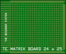
All the circuits can be built on our Matrix Boards. (or this link for the web: Matrix Boards)


15 holes x 40 holes $2.95
or: 15 holes x 40 holes

24 holes x 25 holes $3.60
or: 24 holes x 25 holes
Each hole in the Matrix Boards above has a circular tinned-copper land and the components are joined with fine tinned-copper wire.
These boards are ideal for creating a project that can then be designed on CAD, using the same layout and you will be sure it will work. If you think you can make a perfect CAD board without firstly creating a prototype, you are either an "expert" or fooling yourself.
You must make a prototype to check the performance of anything before launching into a final design.
That's why we use MATRIX BOARDS ourselves.  It's almost 100% guarantee of success. (or this link: MATRIX BOARDS)
Place the components on the top of the board and solder the leads to the lands. The boards can also be used "up-side-down" but this is only for experimenting, when components need to be added and removed until the circuit is operating perfectly. 


Flashing circuits are very interesting. They grab your attention and can be used in many applications.
They consume very little energy and a single cell can last as long as 12 months.
You can flash globes, LEDs and pulse all types of devices such as motors, solenoids and piezo diaphragms.
In this discussion we will cover a number of interesting "oscillator circuits."
They can be adapted for other applications - but to do this you have to know how they work. This is not easy as most of them are quite complex. In fact oscillator circuits are one of the most difficult circuits to understand. But if you read the text, everything will become clear.

Flasher circuits have developed over a long period of time, with many of the earlier designs proving to be unreliable. One of the earlier successful designs is discussed in our article, Spot This Mistake P4 (or use this link for the web: P4).


The first circuit we will cover is the first project you should build, it is:

THE LED FLASHER  K-LF1   $3.10
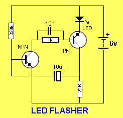
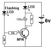
This is a very simple project using a printed circuit board and 8 components. It will flash an ordinary 3mm or 5mm (1/8" or 1/4") LED at a rate of about one flash per second.
 

PARTS LIST
1  -  22R
1  -  1k
1  -  330k
1  -  10n
1  -  10u  16v electrolytic
1  -  BC 547 - NPN
1  -  BC 557 - PNP
1  -  1/4" (5mm) red LED
1  -  LED FLASHER PC

A complete kit for this project is available from Talking Electronics.  (or: Talking Electronics) The circuit has a couple of advantages over a flashing LED you can buy as an individual item. It pulses it with a higher peak current to give a brighter illumination and consumes less average current. This means it will work for a long time on an almost flat battery and cost nothing to run. It can be used for battery equipment to indicate the power is ON or as an ALARM ON indicator. You can use a super-bright LED and get a really bright flash, or an ordinary green, orange or yellow LED to get something better than a flashing red LED.

 
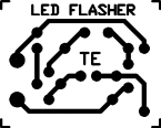
The LED Flasher PC board

THE CIRCUIT
This circuit works on the basis of a high-gain amplifier being driven into saturation (fully turned-on), firstly by the very small amount of current delivered by a high-value resistor and then from energy stored in an electrolytic.
When the energy from the electrolytic has been fully delivered, it cannot keep the amplifier fully turned on and it  turns off slightly. This action removes the "turn-on" effect from the electrolytic and the amplifier begins to turn off. This action continues until the amplifier is fully turned off and is kept in the off state while the electrolytic begins to charge. The off-state is very long and the on-state is very short. This is how the LED produces a brief flash.

Here is the technical description of the operation of the circuit:
When the supply is connected, both transistors are off and the electrolytic charges via the 330k resistor and 22R. When the voltage on the base of Q1 rises to about .6v, the transistor begins to turn on and the resistance between its collector-emitter terminals is reduced. This allows current to flow in the collector-emitter circuit and Q2 is turned on via the 1k resistor. The 10n reduces the effect (the resistance) of the 1k resistor. Q2 conducts and the LED is illuminated. The current through the LED is limited by the 22R resistor and at this point in the cycle a voltage is developed across the 22R. The negative end of the electrolytic is `jacked up' by this voltage and the positive end pushes the charge on the electrolytic into the base of Q1 to turn it on even harder. In a very short time all the energy in the electrolytic has been delivered to Q1 and it cannot hold Q1 ON any longer. The transistor turns off slightly and this has the effect of turning off Q2 a small amount. The LED begins to turn off and the voltage across the 22R reduces. The negative lead of the electro drops a small amount and so does the positive lead. This action continues around the circuit until Q1 is fully turned off. This turns off Q2 and the LED is extinguished. The cycle starts again by the 10u charging. The charge-time is considerably longer than the discharge time and this gives the LED a very brief flash.

CONSTRUCTION
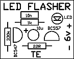
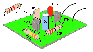
All the parts mount on a small PC board and it has an overlay (all our boards have overlays) as shown in the diagram below:


Mounting the components

This makes construction very easy and all you have to do is bend the leads of the components so they pass down the holes in the board. The resistor leads are bent to 90° and are pushed all the way down so they rest on the board. The leads are then bent slightly to hold them in place while the leads are soldered. Fit the three resistors in this way and you are ready for the two capacitors. The 10n can be fitted either way around but the 10u electrolytic must be fitted so the positive lead goes down the hole marked with a "+." The positive lead is the shorter of the two leads and the negative lead is marked on the side of the body of the component with a " —"
The two transistors are next and it is important not to mistake the PNP for the NPN. They both look identical. Check with the parts list for the types you have been given in the kit. Fit the leads down the holes so that the transistor is 2mm (1/8") from the board and bend the leads slightly so it does not fall out when the board is turned over and soldered. Finally the LED is fitted to the board.


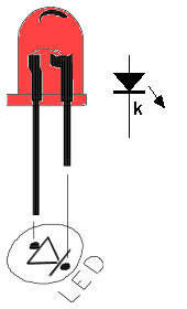
Fitting the LED

Refer to the diagram above for the identification of the cathode lead. Keep the LED above the board so it can be clearly seen. Solder a short length of red and black wire to the board and to 4 cells to complete the project. You can use almost any old cells for the 6v supply and let the LED FLASHER use them up completely.


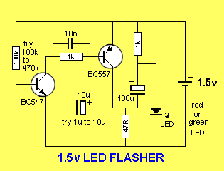
1.5v LED FLASHER
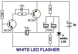
The next circuit flashes a LED and uses a 1.5v supply. The LED does not turn on via the 1k resistor because the characteristic voltage of a LED is between 1.7v and 2.3v, (depending on the colour).  It turns on when the 100u is "jacked up" by the collector of the BC557.
The circuit is a charge-pump design. This is where a capacitor (electrolytic) is allowed to charge and is then raised higher and allowed to discharge into a load. The load sees a voltage that can be higher than the supply.
This is the case with this circuit.
The two transistors operate as a high-gain amplifier with the output being the 47R. The cycle starts with the first transistor being turned on via the 100k. This action also charges the 10u until 0.75v appears on the base of the transistor.
This turns on the second transistor and the negative end of the 10u is raised when the BC557 turns on. This raises the positive end of the 10u and the first transistor turns on even more. This action continues until the first transistor is fully turned on and the BC557 is fully turned on. The voltage across the collector-emitter terminals of the BC557 will be small and about 1v will appear across the 47R. This voltage "jacks up" the 100u and since it is fully charged via the 1k resistor, it will present a voltage of about 2.5v to the LED. Any voltage over 1.7v will turn on a red LED and a green LED will turn on at 2.3v. The energy in the 100u is now passed to the LED to illuminate it.
The flash is very brief due to the operation of the two-transistor amplifier. Although the energy in the 100u will produce a brief flash, the timing of the two transistor circuit is even faster and it provides the duration.
The actual duration of the flash depends on the time the two transistor amplifier can be in a fully turned-on state. This is governed by the charging of the 10u electrolytic.
When the base of the first transistor sees 0.7v, the two transistors start to turn on by a process called REGENERATION. This is explained further in our article: REGENERATION, in Circuit Tricks. Regeneration is a condition where a circuit turns on more and more without any external assistance.
And this is what happens in this circuit.
The 10u is "jacked up" by the BC557 turning on and it delivers a current to the base of the BC547. Initially it delivers its energy to the base but very soon is is higher than 0.7v and it is fully discharged. The electrolytic now starts to charge in the reverse direction and this process continues to keep the BC 547 turned on. It charges very quickly in the reverse direction as the charging path is the emitter-collector junction of the BC557 and base-emitter junction of the BC547. When it is nearly charged, the current-flow reduces and this turns off the BC547 very slightly. This turns off the BC557 slightly and the 10u is "lowered." This puts less "turn-on" on the BC547 and the two transistors start to turn off very quickly.
The 10u is now charged in the reverse direction and a negative voltage is presented to the base of the first transistor. This voltage is is gradually reduced by the electrolytic charging via the 100k and that's why the circuit has a very long off cycle.
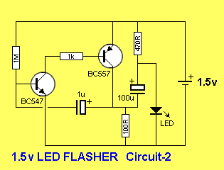
Two circuits are shown. They use slightly different components to produce the same results.
The only critical value is the 100R. The circuit will not work with a value higher than about 150R. It needs a low value so the BC557 transistor is turned on to a high level before a voltage is developed across the 100R. If the value is too high, a voltage will be developed across this resistor when the BC557 is turned on a small amount and this voltage will be sent to the BC547 to turn it on too. The two transistor will sit in a conditions that they are both turned on and the circuit will freeze.
The circuit has to function such that the BC547 is turned on to its maximum when the electrolytic is pulled HIGH. This transistor will now be turned on by the current delivered by the 100k (or 1M) plus the charging current of the electrolytic.  As the electrolytic charges, the current into the base of the BC547 will fall and the transistor will turn off slightly. This slight turn-off must be passed to the BC557 to turn it off slightly too and lower the "turn-on" effect of the electrolytic. It is the 47R (or 100R) that is pulling the electrolytic down to the 0v rail and if this resistor does not have sufficient "pull-down" effect, the cycle will not continue. When this resistor has a low value, the BC557 must deliver a high current and it must be turned on via a proportionally high current into the base. This current comes from the BC547 and it needs a proportionally high current into its base to provide this condition. We are only talking about fractions of milliamps and microamps, but these conditions must be met for the circuit to work.


The next circuit replaces a flasher chip. These are no longer available but many circuits use them. Here's the alternative:

THE LM 3090 FLASHER CHIP
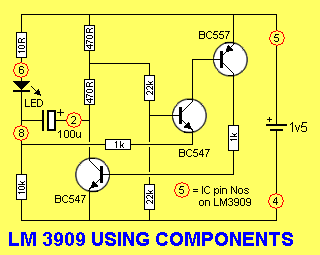
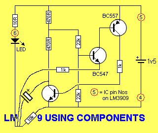
The LM3909 flasher chip has been discontinued for a number of years and the following circuit can take its place:

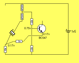
When power is applied, the 100u is uncharged and zero voltage is across its terminals.
It is charged via the two 470R resistors and 10k resistor and these three resistors create a voltage divider across the 1.5v supply such that the voltage on the top of the 10k resistor is
about 1.4v
This makes the emitter of the middle transistor about 1.4v and thus it is not turned on.
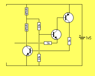
The BC 557 is also not turned on and the first transistor is also not turned on.
As the 100u charges, the voltage across the 10k resistor decreases and the middle transistor begins to turn on.
This turns on the BC 557 and the first transistor begins to turn on very quickly and very soon it is fully turned on.
This effect brings the positive of the 100u towards the 0v rail and the best way to see how the voltage across the electrolytic adds to the 1.5v supply to produce a voltage above 2v, is to refer to the following diagram:


The voltage on the top of the 10k resistor actually goes about 1v below the 0v rail and makes the 10k dip down as shown in the diagram above.

There is one very important requirement when designing an oscillator.
The timing capacitor must be discharged.
In other words the circuit must create a state that discharges the capacitor and remains in that state until the capacitor is fully or almost fully discharged. If it is not discharged, it cannot be charged again!

HOW THE CIRCUIT WORKS
So, let's start at the beginning:
The analysis of the circuit starts at the base of the middle transistor. The voltage at this point is approx half the supply voltage when the circuit is turned on as no transistor is conducting and the electrolytic is discharged.
Since the voltage on the circuit is only 1.5v, the LED is a very high impedance at this voltage as it does not activate until the voltage is above its characteristic voltage of approx 1.7v.
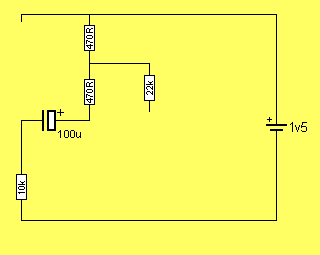
The only components that are effectively "in circuit" are shown in the following diagram, and the electrolytic begins to charge:


Charging the electrolytic

When the circuit is first tuned on, the electrolytic has zero voltage across it and the 10k and 470R resistors are in series. About 0.13v is across the two 470R resistors and 1.37v is across the 10k resistor.
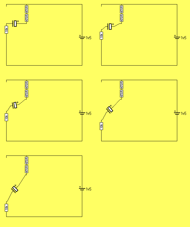
As the electrolytic charges, the voltage across the 10k reduces.
The following animation shows how the voltage across the 10k changes:


The electrolytic charging

As the electrolytic charges to about 1.2v, the middle transistor begins to turn ON as the voltage on the top of the 10k resistor drops from 1.37v to about .17v.


The voltage on the transistor turns it ON

The voltage between the base and emitter of the transistor is 0.58v and the transistor begins to turn on.
The transistor used in the prototype turned on at 0.38v and this is the secret behind the circuit operating down to a supply voltage of about 0.8v
In the diagram below, the middle transistor is turned on slightly and this turns on the third transistor. The third transistor turns on the first transistor.


All the transistors are turned ON

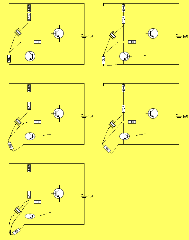
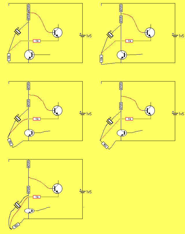
The first transistor pulls the lower 470R resistor towards the 0v rail and the positive end of the electrolytic. The negative end is also pulled down as shown in the following animation:


The electrolytic getting pulled to the 0v rail

Here is the clever part:
As the electrolytic charges, the emitter of the middle transistor is being pulled down and the base is being pulled down at half the rate. This means the voltage between the base and emitter is widening and the transistor is being turned on MORE. 
This is called REGENERATIVE ACTION. The action continues until the first transistor is fully turned ON.


The voltage between base and emitter increases


Here is a circuit using the LM 3909:

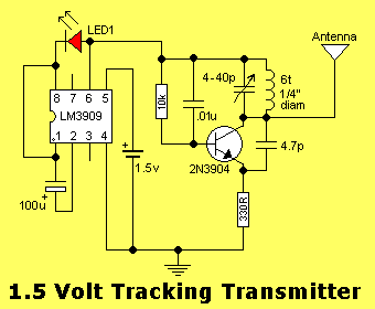
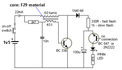
The FM transmitter section above operates continually from the 1.5v and the "flasher chip" provides a slight interruption to create a "beep" on the airwaves which is really the transmitter shifting off frequency and the carrier being lost. It does not use the "jacked-up voltage" feature of the chip.
If a load other than a LED is connected to the circuit, the electrolytic will not charge.
The circuit relies on the fact that the LED is an "open-circuit" when the supply voltage is below the characteristic voltage of the LED (approx 1.7v).
The circuit, however, can be used as an oscillator to drive other loads providing the LED and electrolytic are retained as they provide the "timing component" and "load."
This makes the circuit very wasteful with current if required for other applications.
There are other circuits more suitable, as you will see.

Next, we have the astable multivibrator, or FLIP FLOP [pronounced (h)ay stable] - meaning it has unstable states. In this case, two unstable states.

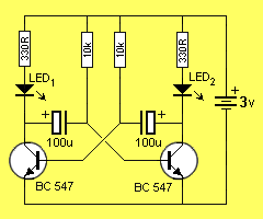
THE FLIP FLOP
This is the simplest circuit capable of alternately flashing two LEDs. The flash-rate is determined by the two 10k resistors and two 100u electrolytics.
The flash-rate can be increased or decreased and one LED can be made to flash brighter by altering the 4 components.
The operation of the circuit is fully discussed in the Basic Electronics Course P17 & P19 (subscription needed) and in 5 Projects P16. (use this link for the web: 5 Projects)
It can be purchased as one of the kits in 5 Projects. (use this link for the web: 5 Projects)
This circuit does not have the advantage of the two described above. It does not pulse the LED with a high current for a short period of time and thus it is not as efficient as the two above. When a LED is pulsed with a high current for a very short period of time, the output is almost as bright as a constant, lower-current.


THE FLIP FLOP
 

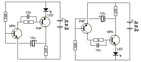
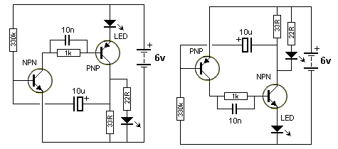
Here are some Flashing LED circuits from "200 Transistor Circuits' eBook. The first 4 circuits show how to change an NPN transistor for PNP.


UNCONVENTIONAL CIRCUITS:
The following circuit converts 1.5v to a voltage that is higher than the reverse break-down voltage of the emitter-collector junction of the BC547. When this voltage is reached the junction breaks-down and creates a low voltage across it. This allows the voltage on the 100u to pass to the white LED and create a flash. The voltage across the 100u drops and the junction comes out of conduction and the cycle repeats.  

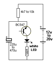
The next circuit uses the same "Junction Breakdown"  phenomenon but this time the high voltage is supplied by a 12v to 20v battery. 
All transistors have a single junction or two junctions between each pair of leads. They are called a "PN" junction or a PNP junction or an NPN junction - depending on which leads are selected. The junctions between each pair of leads behave differently, however the junction(s) we are interested in, is between the collector and emitter leads.
When a voltage is applied to these leads in the reverse direction, an unusual thing happens.
As the voltage is increased, the junction suddenly breaks down and a high current will flow , according to the energy available from the electrolytic.  This occurs at a voltage of between 12v and 20v, (some transistors will require a higher voltage) depending on the type of transistor and the manufacturer. When the voltage across the leads falls, the current stops.
In other words, the resistance between the two leads decreases when the voltage rises to between 12v and 20v (and the voltage across the two leads is about 0.5v and this is a characteristic of the junction). When the supply-voltage drops, the junction-resistance increases and the electrolytic charges.
This feature can be used to flash a LED as shown in the following diagram:


Flasher circuit using "Junction Breakdown"

The circuit above is very unreliable and only works with some transistors. The voltage is very important. It must be high enough to cause the junction(s) between the emitter and collector leads to breakdown.
The flash-rate will depend on the value of the top resistor and the electrolytic and also the voltage at which the transistor break-down.  The circuit consumes less than 1mA and the 100R prevents a high current flowing through the LED (from the electrolytic). Without the 100R, the LED is destroyed instantly. 
The circuit is a very good demonstration of breakdown but due to the high supply voltage needed, it is not a practical design. The previous circuit should be used.

LAMP FLASHERS
The following circuits will flash a car globe for a Warning Beacon.
It uses two Darlington transistor in a flip-flop circuit. The layout must be kept "tight" (thick wires) to be sure it will oscillate. A complete kits of parts and PC board costs $5.00 plus postage from: Talking Electronics. Email HERE for details. 


Warning Beacon

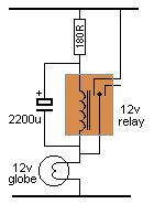
The following simple circuit flashes a globe at a rate according to the value of the 180R and 2200u electrolytic.


Simple Flasher

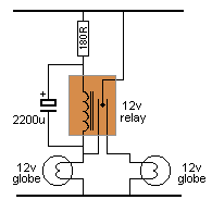
The Flasher can alternately flash 2 globes as shown in the following circuit. You will need to adjust the value of the components to get an equal flash-rate for the two lamps. It is a mechanical equivalent to the flip-flop circuit above.


Dual Flasher


7-1-2011


구체적인 자료는 USB 표준 문서를 보시기 바랍니다...

핀맵에 관한 부분만 발췌한 내용입니다...


[출처] usb 4핀 핀맵 |작성자 아라


출처 : 

http://kin.naver.com/qna/detail.nhn?d1id=5&dirId=5020404&docId=22914256&qb=dXNiIO2VgOuntQ==&enc=utf8&section=kin&rank=1&search_sort=0&spq=0&pid=gpQuOc5Y7u0ssbWYnZdssc--301106&sid=TpeDXdVvl04AAHdRGzw


          (1) 파워 서플라이의 동작 원리...


         1) 파워 서플라이(Power Supply)란?...


   a) 파워 서플라이라는 것은 가정용의 교류(AC) 전류를 받아들여서, 컴퓨터에 필요한 3.3v/5v/12v 등의 직류(DC) 전류를 만들어주는 장치이다.- 컴퓨터는 결국 전기가 있느냐(1), 없느냐(0)의 (2 진수) 체계로 의사 소통을 하는 기계이므로, 전류는 컴퓨터에게 있어서 피나 식량에 해당되는 핵심 중의 핵심이다.- 따라서 전기를 공급해 주는 파워 서플라이(PSU)는 어떻게 보면 CPU나 RAM보다도 더 중요한 부품이므로, 보통 (컴퓨터의 심장)이라고도 한다. 

   b) 위의 그림은 컴퓨터에 관심 있는 사람이라면, 한 번쯤 들어 봤을 법한 (시소닉)이라는 회사에서 만든 500W 급의 파워 서플라이이다.- 시소닉에서 만든 (고급형) 파워 서플라이는 따로 있고, 위에 소개된 것은 (중저가) 형으로서, 2008년 8월 현재 80,000 원 내외이면 살 수 있는 제품인데, 개인적으로 가장 많이 추천해 주는 제품이기도 하다.- 효율성은 물론이고, 안정성 면에서도 자타가 인정하는 제품이고, 가격도 그리 크게 부담되는 정도는 아니므로, 앞으로의 설명은 이 제품을 기준으로 진행할 계획이다(제품 이름;SS-500ET-공급사;GMC).

이 제품에 관심이 있으면,This로 가서 제품 정보를 더 보고, 거기에서 제품 이름 옆에 있는 [리뷰]라는 버튼을 누르면, 리뷰에 관한 정보도 볼 수 있으므로 참고하시라.^^.


            2) 파워 서플라이의 작동 원리...


   ***위의 그림은 앞에서 소개한 시소닉의 SS-500ET라는 제품의 내부 구조이다.

    ***아래에서는 위의 그림에 알파벳을 붙인 순서대로 설명을 할 것인데, 이 순서가

    ***바로 파워 서플라이가 가정용 교류(AC) 전류를 받아서, 컴퓨터에 필요한 직류

    ***(DC) 전류로 바꿔서 내보내는 과정이므로 관심있게 봐 주기 바란다.


      a) EMI 필터부-- 파워 서플라이의 전원 코드가 꼽히는 가정용 콘센트에서는 보통 교류(AC) 220V가 공급된다. 그런데, 이 교류 전기는 매번 위 아래로 파동을 일으키는 것은 물론이고, 여러 원인에 의해서 컴퓨터에 해로울 수 있는 잡음 신호들을 발생시킨단다.- (EMI 필터부)라는 것은 가정용의 교류 전기를 파워 서플라이에 공급하는 초입 단계에서 그런 신호 잡음들을 걸러 주는 역할을 한다.-그리고 거꾸로 파워 서플라이의 (직류-직류 스위칭) 때 발생하는 (스위칭 잡음)을 가정용의 교류 입력 라인으로 역류하는 것도 필터링해서 막아주기도 한다.


      b) 교류→직류 정류부-- (EMI 필터부)를 통과한 교류는 (교류-직류 정류부)를 통해 일단 311V의 임시 직류로 변하게 되는데, 다음 과정을 거친다.- ① 정류 회로-초당 50~60Hz로 (+)와 (-)를 번갈아 오가면서 진동을 하는 교류에서 (정류 다이오드)을 통해서 (+) 극성만을 걸러내는 과정이다. 비록 (+) 전류만을 걸렀다고는 해도 아직까지는 전압이 변하는 상태이므로, 이 과정을 거친 전류를 (맥류)라고 한다.→② 평활 회로-일정한 전압 이상이 들어오면, 기준 이상으로 들어 오는 전하를 충전시키고, 그 이하로 전압이 들어오면 충전시켜 뒀던 전하를 방전시키는 방법으로, 항상 (일정한 전압)을 유지시켜 주는 (정류 콘덴서)를 이용하여, 맥류를 일정한 전압에 비슷하게 만들어주는 과정이다.→③ 정전압 회로- 평활 회로를 통과한 맥류라고 해도, 아직은 건전지 등에서 나오는 것같은 일정한 직류가 되진 못한다. 그래서 최종적으로 (정전압 다이오드)와 (트랜지스터)로 이루어진 정전압 회로를 거치게 함으로써, 안정적이고 일정한 직류를 만들어 주게 된다.

보통 (고급 PSU)일수록 이 정전압 회로에 신경을 더 많이 써서, 비용 상승의 원인이 된다.


      c) 직류 →직류 스위칭 변환부--(교류/직류 정류부)를 통해 일정한 직류로 변환된 전기를 다시 컴퓨터에서 필요로 하는 3.3V/5V/12V 등의 직류로 감압시켜주는 과정이다.-① 임시 직류로 바뀐  걸 (감압 트렌스)를 통해 PSU가 제공하는 최대 전압인 +12V로 만든다.→②그리고 -12V는 +12V를 역방향으로 출력시켜서 만들고.→③ +5V와 +3.3V는 +12V를 다시 (DC 감압 트렌스)를 이용해서 감압시켜서 만들고.→④-5V와 -3.3V는 +5V와 +3.3V를 역방향으로 출력시켜서 만들어 낸다.

-이렇게 컴퓨터에서 필요로 하는 +12V/-12V/+5V/-5V/ +3.3V/-3.3V 등의 직류 전압을 만들어내는 과정은 보통 여러 개의 Switch들을 변환시키는 방식으로 처리되므로, (스위칭 변환부)라고 한다.


    d) 출력 필터 및 출력부--① 컴퓨터의 부품들은 전기의 질에 매우 민감하다. 따라서 (직류/직류 스위칭 변환부) 과정을 통과한 전기를 그냥 내보내지 않고, 최종적으로 한 번 더 필터링을 해서 각 부품들의 규격에 맞는 전압으로 맞춰서 출력을 시키는 과정이 (출력 필터 및 출력부)인 것이다.→② 이렇게 출력할 준비를 완전히 끝내게 되면, PSU는 비로소 Power good signal 신호를 메인보드로 보내게 되고, 이 신호를 받은 메인보드의 Timer Chip은 CPU에게 Reset signal 신호를 보내게 된다. 안정성이 확보되었다 싶으면 Reset signal을 끊어줌으로써, CPU가 드뎌 깨어나서 Clear 작업을 하고, Bios의 (FFFF:0000)

주소를 메모리로 읽어들임으로써, 컴퓨터 시스템의 Booting 과정이 시작되는 것이다.

      e) 기타 회로들---위에선 파워서플라이가 구동되는 기본 회로에 대해서만 설명했다.

그러나, PSU가 제대로 만들어졌다고 하기 위해선,전력 효율과 전자파 감소 등에서 중요한 역할을 하는 Active PFC 회로갑자기 정전이나, 낙뢰 등으로 과전압이 발생했을 때 시스템을 보호해 주는 과전압 방지회로 등, 갖춰져야 할 것들이 더 있음을 알아야 한다.

-메이저급 회사에서 만든 PSU와 묻지마(듣보잡) 회사에서 만든 PSU는 그런 안전 회로들을 얼마나 잘 구비했느냐와, 4 단계의 기본 회로를 구성하는 각종 부품들을 얼마나 믿을만한 것으로 썼느냐에서 차이가 나는 것이므로, 평소에 검색 등을 통해서 정보를 얻어야 한다.


          (2) 파워 서플라이의 전압 종류...


       1) 파워서플라이는 가정용 교류(AC) 전압 220V를 각 부품의 용도에 맞게 +12V/-12V/+5V/-5V/+3.3V/-3.3V 등의 직류(DC) 전압으로 만들어 주는 장치라고 했다.- 위  그림은 유명한 시소닉이란곳에서 만든 고급형 PSU인 SS-500GM과 중저가형 PSU인 SS-500ET의 옆면에 붙어 있는 스티커이다.- 이 스티커를 보면, 해당 PSU가 어떤 종류의 직류 전압을 제공하는지 알 수 있다.

       2) 위의 (작동 원리)에서는 -12V/-5V/-3.3V  등에 대해서도 언급했는데, 이것들은 일부 회로의 신호 전달이나 컴퓨터 케이스에 붙어 있는 스피커 등을 구동하는데 썼던 것들이다.-그런데 요즘은 그 쓰임새가 거의 없어서, 구색을 맞추는 차원에서 -12V 정도만 뽑아서 표시해 주는 추세이다.

       3) 그럼 가장 중요한 +12V/+5V와 +3(3.3)V 등에 대해서 그 용도를 설명해 보겠다.

  a) +12V---모터가 돌아가는 것에 쓰이는 것이라고 보면 된다. 즉 메인 보드에 연결되지 않고, HDD, ODD, FDD 등에 직접 연결되어서 그 기기들의 모터를 구동시키거나, 아님 컴퓨터 케이스의 Fan의 모터를 구동시키는 데 쓰이는 게 +12V이다.-그리고 메인보드의 24 핀 커넥터의 +12V 라인도 이걸 끌어다 쓴다. 요즘은 CPU나 VGA 등이 고성능화되면서, +12 V 라인의 중요성이 커지고 있다.

   b) +5V---HDD나 Power의 작동 LED를 켜고, 마우스와 키보드 등 구동할 때 이 +5V를 쓴다.

     -그리고 역시 메인보드의 24핀 커넥터의 +5V라인에서도 이것을 끌어다 쓰고 있다.

   c) +3(3.3)V---메인 보드에 있는 각종 IC 회로 등을 구동시키는데 쓰는데, 메인보드에 있는 24 핀 커넥터의 +3.3V 라인을 통해서 끌어다 쓰게 된다.- USB 장치 등도 이 전압을 사용하고 , - 이제는HDD의 대세가 된 SATA 방식의 HDD에서도 +12V/+5V 외에 이 +3.3V가 사용되는 것을 볼 수 있다.


      4) +5V sb 전압의 용도...

   a) 위 스티커 그림을 보면, 젤 오른쪽에 (+5V sb)라는 항목이 보인다. 여기서 (sb)는 Stand By의 약자로서, 쉽게 풀어보면 (+5V 대기 전압)이란 뜻이다. 그렇다면, 이 대기 전압의 용도는 뭘까?

   b)+5Vsb는 전원 공급 상태가 정상적일 때, 상시로 활성화되는 대기전압이다.- 이런 대기 전압이 필요한 이유는, 4 개의 주요 DC 출력단(+3V/+5/+12/-12V)이 꺼져 있거나(Off), 비 활성화 상태일 때도 작동 대기 상태로 남아 있어야 하는 회로들이 있는데, 그런 것들에 전기를 공급할 때 쓴다.

   c) 그리고 이 +5Vsb 대기 전압은 Lan Card나 Modem의 연결 상태를 상시로 확인하기 위해서도 사용되고 있으며, 외부 침입 탐지나 파워 서플라이의 보호 등을 위한 활동에도 쓰이게 된다. 

  d) 또 Windows 등의 OS나  각종 Application 등에서 컴퓨터의 전원을 켜거나 끌 때도 이 전압을 쓰는데, 시모스 셋업의 Power Management Setup에서 이 전압의 사용 유무를 설정할 수도 있단다.


        5) +12V 라인의 중요성...

   a) 위에서도 잠깐 언급했지만, 요즘은 CPU나 VGA 등이 고성능화되면서, VGA 하나 만으로도Full Load시에 200W 이상의 전력을 쓰는 경우도 있다.- 이런 추세에서 파워서플라이가 공급하는 전압들 중에서 가장 높은 전압인 +12V 라인의 전압의 중요성이 갈수록 커지고 있는 것이다.

   b) 파워서플라이 관련 글을 읽다 보면, (정격 출력이 똑같이 500W인 PSU들이라고 해도, 평소 자기가 고성능의 VGA 등을 쓴다면, +12V Rail이 강화된 파워서플라이를 사용해야 한다)란 글을 볼 때가 있다.- 이 얘기는 PSU가 똑같이 정격 출력 500W를 뽑아내는 것이더라도, 상대적으로 +12V 라인 쪽에서 많은 전류를 뽑아낼 수 있는 것이 고성능의 VGA 등을 쓸 때 보다 유리하다는 뜻이다.

   c) 위에서 비교한 고급형 SS-500GM과 중저가형 SS-500ET의 스티커를 보면, 다른 항목들은 다 같은데, 고급형인 SS-500GM이 두 번째 +12V 라인에서 뽑아주는 전류가 18A로, SS-500ET의 그 라인의 17A보다 큰 걸 알 수 있다. 그래서 두 개의 +12V 라인(레일)을 합쳐서 출력하는 Combined Output이 SS-500GM은 420W인 반면, SS-500ET는 408W로, 상대적으로 고급형인 SS-500GM가 +12V라인이 강화되어 있음을 알 수 있다.-현재 SS-500GM은 115,000 원 정도이고, SS-500ET는 82,000 원 정도로, SS-500GM이 약 33,000 정도 더 비싸게 팔리는데. 이렇게 비싼 이유는 +12V 레일을 강화하는데 드는 비용과  콘덴서 등의 내부 부품을 더 고급형으로 쓰고 있기 때문이다.

   d) 또 한 가지 짚고 넘어갈 것은 SS-500ET가 중저가형이라고 해서, 고급형인 SS-500GM보다 불안정하거나 믿을 수 없단 뜻은 아니다.- 최소한 시소닉이란 회사에서 만들었다면, 비록 중저가형이라고 해도 믿을 수 있다.- 지금 이 글을 쓰고 있는 컴퓨터(Pentium 4 2.80GHz(노스우드))는 조립한지 5 년 정도 된 것인데, 조립할 때 시소닉의 중저가형 350W 파워서플라이(약 60 000원)를 선택했었다(그 때 똑같은 350W 짜리지만, 고급형으로 80,000 원이 넘는 제품도 있었음). 그런데, 이 넘은 5 년 동안 단 한번의 문제도 일으키지 않았고, 시스템을 고장낼 수도 있는 (정전 사태)를 여러 번 겪으면서도 거뜬하게 내 컴퓨터 시스템을 잘 보호해 줘서 애착이 많이 가는 PSU이다!^^.


          (3) 파워 서플라이 커넥터들의 구조...


       1) 지금까지 PSU의 작동 원리와 그런 과정을 통해서 얻어지는 전압의 종류 등에 대해서 간단하게 알아 봤는데, 마지막으로 파워 서플라이에서 제공되는 기본 커넥터들의 구조를 보면서, +12V/+5V/+3.3V 등의 전압들이 실제로 사용되고 있는지를 확인하면서 이 글을 끝마치려고 한다.


        2) 위의 그림에서 a)로 표시한 것이 (4핀 커넥터)이다.- 이것의 용도는 IDE 방식의 HDD나 ODD 등에 전원을 공급하고, 때론 컴퓨터 케이스의 Fan을 구동시키는 데 쓰이고, 새로운 HDD로 자리잡은 SATA 방식의 HDD를 위한 전원선이 없을 때, 변환 커넥터를 연결해서 SATA용 HDD를 위한 전원을 뽑을 때도 쓴다.- 그리고 요즘 VGA(그래픽 카드)가  고성능화되면서, VGA를 설치할 때, 6핀 보조 전원을 요구하는 경우가 많은데, PSU가 구식이라서 6핀 보조 전원을 끼울 수 있는 6핀 커넥터가 따로 없다면, 이 4핀 커넥터를 6핀 보조 커넥터로 변환시켜서 쓰기도 한다.- 위의 그림을 잘 보면, 4핀 커넥터에 +12V와 +5V가 쓰이고 있는 것을 볼 수 있다.


       3) 그림 b)로 표시된 것은 플로피 디스켓 드라이브(FDD) 용의 4 핀 커넥터이다.- 요즘은 FDD를 거의 쓸 일이 없지만, 가끔 필요할 때도 있으므로, 최신 PSU에선 간접 변환 커넥터 방식으로라도 FDD용 4 핀 커넥터를 제공하고 있다.- 이것에서도 역시 +12V와 +5V가 쓰이고 있다.


       4) 그림 c)는 (4핀 보조 전원) 커넥터이다.- 컴퓨터를 처음 조립할 때, 24 핀 메인 커넥터만 끼우고, 4핀 보조 전원 커넥터를 끼우는 것을 잊어서, 컴퓨터를 작동시키지 못하는 걸 종종 볼 수 있다.- +12V의 쓰임새가 많아지면서, 그것을 더 보강해 주기위한 커넥터이므로, 컴퓨터를 조립할 때 반드시 연결시켜 줘야 하는데, 그림을 보면 +12V 핀이 2 곳에서 쓰이고 있음을 알 수 있다.


       5) 그림 d)는 이젠 HDD의 기본 방식으로 자릴 잡은 SATA  HDD를 위한 전원선 커넥터이다.

         그림에선 잘 안 보이는데 , 위에서부터 (+3.3V 핀 3개→COM 핀 3개→+5V 핀 3개→COM 핀이 다시 3개→마지막으로 +12V 핀이 3개)가 있어서, 총 15 개의 핀이 있는 (15핀 커넥터)이다.-  COM은 Ground(접지)용의 (-) 핀을 말한다.- 요즘 새로 만들어진 PSU들은 최소한 2 개 이상, 많게는 10개 이상까지 이 SATA용 HDD를 위한 15핀 전원 커넥터를 가지고 있고, SATA용 HDD를 살 경우엔 15핀 커넥터가 없거나 부족할 것에 대비해서, (4핀 커넥터)를 (15핀 커넥터)로 바꾸는 변환 선을 따로 제공하기도 한다.-이 15핀 커넥터에선 +12V/+5V/+3.3V 전압이 모두 쓰이고 있는 것이다.


       6) 그림 e) 메인 보드에 전원을 공급하는 중심 역할을 하는 (24핀 커넥터)이다.- 오른쪽에 확대해 논 그림을  보면, 여기에는 +12V/+5V/+3.3V 전압이 다 쓰이고 있다.- 요즘 CPU나 RAM 등 주요 부품을 보면, 작동 전압이 1.5V 내외이다. 따라서 메인보드는 +12V/+5V/+3.3V 등을 그냥 공급하지 않고, 각 부품에 맞게 재조절을 해서 CPU나 RAM 등에 보내 준다.- 그리고 예전의 Pentium 4 시절에는 메인 전원이 20핀 커넥터를 쓰고 있었는데, 요즘은 이렇게 24 핀 커넥터로 바뀐 상태이다.

만일 예전의 20핀 커넥터를 쓰는 파워서플라이라면, 시스템에서 전력을 크게 요하는 경우가 아닌 한 위쪽을 서로 맞춰, 메인보드의 24핀 커넥터에 PSU의 구식 20핀 커넥터를 끼워도 컴퓨터가 작동은 된다고 한다.-이런 작동이 가능한 것은 24핀 커넥터에서 새로 추가된 4 개 핀은 제일 아래쪽에 있는 (+12V/+5V/+3.3V/COM)들인데, 이것들은 이미 예전의 20핀 커넥터에도 다 있던 라인이고, 그것들을 보충하는 차원에서 추가한 것이므로, 20핀 커넥터의 PSU라도, 믿을 만한 제품이라면, 요즘의 24핀 커넥터를 가진 메인 보드에도 사용은 할 수 있다는 뜻이지만, 그렇게 권장할 만한 것은 못된다.


       7) 파워 서플라이 (단독 작동 테스트) -- 그림 f)의 24핀 메인 커넥터를 확대해 논 것을 보면, 16번 핀인 PS-ON과 15번 핀인 COM를 빨간선으로 연결시킨 걸 볼 수 있다. 컴퓨터를 사용하다보면, 조립할 때 PSU가 정상적으로 작동되는지 테스트해보고 싶을 때도 있고, 조립후 사용하다가 컴퓨터에 문제가 생겼을 때, 그 원인이 PSU인지를 테스트해 볼 일도 생긴다.- 이럴 때는 PSU의 24 핀 메인 커넥터를 메인 보드에 연결해서 케이스의 Power 스위치로 작동시켜 보는 것이 아니라, PSU를 메인보드와 완전히 분리시켜서, PSU가 정상적으로 작동하는지 단독 테스트해 봐야 할 때도 있다.- 이땐 메인보드에 끼웠던 24핀 메인 커넥터를 빼서, 위에 표시한 두 핀을 (양쪽 끝만 피복을 벗긴 전선)으로 연결시켜주고, 파워서플라이의 전원선을 가정의 콘센트에 끼운 담에 PSU의 뒤쪽에 있는, (1/0)으로 되어 있는 PSU 작동 스위치를 켜서(1로 스위칭), PSU의 정상 유무를 테스트할 수 있다. 이때 연결에 사용된 전선의 피복이 벗겨진 부분을 만지면 감전되므로 조심해야 한다.-그리고 COM 단자는 15번 핀을 쓰지 않고, 그 아래쪽에 있는 17번 핀의 COM 단자를 써도 상관없다.


-----------------------------------------------------------------------------------

***결론***

허접하면서 길기만 한 글을 여기까지 읽으면서 따라오시느라 고생하셨다.^^.

이런 글을 처음 읽으시는 님이라면, 당신히 어렵게 느껴질 것인데, 다음 사항은 꼭 알고 넘어가자.

  1) 컴퓨터에서 파워 서플라이는 무쟈 중요하므로, 돈을 아끼지 말고 믿을 만한 제품을 구매하자.

  2) 가정용 220V 교류(AC) 전압은 (4 단계)를 통해, 컴퓨터에 필요한 직류(DC) 전압으로 변환된다.

  3) PSU에서 이상이 없다는 Power Good Signal 신호를 보내야 시스템의 Booting이 시작이 된다.

-즉 만일 PSU가 내부적으로 이상 있다면, 제 아무리 비싼 컴퓨터라도 부팅 자체가 안 된단 뜻이다.

  4) 점차 CPU나 VGA가 고성능화되는 요즘, +12V 라인의 중요성이 커지고 있고, 따라서 고출력의

파워서플라이인 경우에는 +12V Rail(Line)을 무려 독립적으로 4 개 이상 가지고 있는 PSU도 있다.

(글 중에 잘못된 곳이 있으면, 언제든지 지적해 주세요...확인하고, 감사한 맘으로 고치겠슴다^^)

------------------------------------------------------------------------------------


+ Recent posts